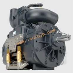
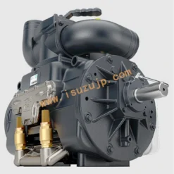
PRODUCT DESCRIPTION
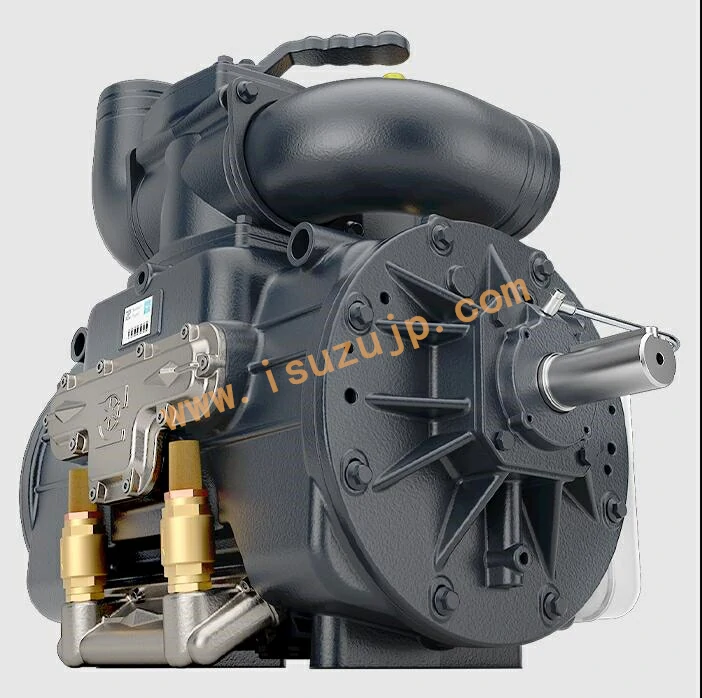
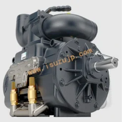
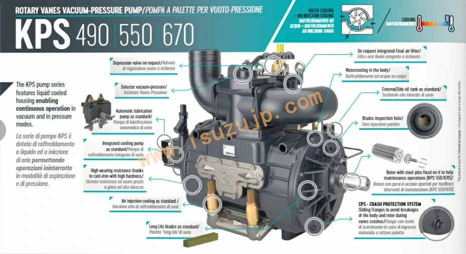
The Roots KPS 490 vacuum pump series features liquid-cooled housing enabling continuous operation in vacuum and in pressure modes.
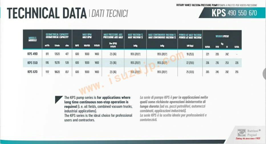
The KPS pump series is for applications where long-time continuous non-stop operation is required (i.e. oil fields, combined vacuum trucks, industrial applications).
The KPS series is the ideal choice for professional users and contractors.
STANDARD FEATURES
Automatic lubrication (2,3 or 4 points), cooling pump, 4-ways valve, Poppet Check valve, Side outlets with revolving elbows, Long Life Blades, Crash protection System Air Injection cooling, predispositon integrate air filter
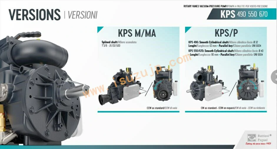
Available hoses connections: Ø 76 mm (3”) / Ø 80 mm / Ø 100 mm (4”)
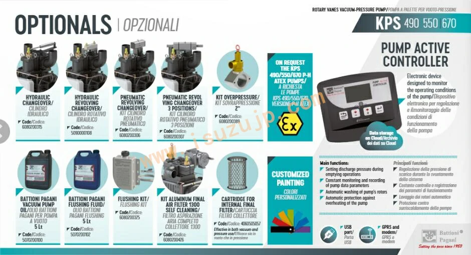
On request, it is possible to have the KPS 490-550-670 ATEX pumps
roots pump Specification:
| product | KPS 490 | |
| geometric capacity | m3/H | 811 |
| L/min | 13520 | |
| cfm | 477 | |
| The number of revolutions (max.) | M/HM | 600 |
| P/D/High | 1400 | |
| pressure bar / PSI(max.) | 2.5 (36) | |
| Vacuum % (inHg)(max.) | 95% (28.5 inches) | |
| Continuous Vacuum % (inHg)(max.) | 95% (28.5 inches) | |
| Power vacuum kilowatts (HP)(max.) | 19 (25.5) | |
| WeightKG
| M. | 221 |
| p. | 205 | |
| D. | 205 | |
| H. | 242 | |
| HM. | – | |
Roots KPS Vacuum pumps Structural design drawings:
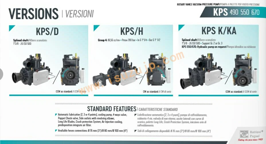
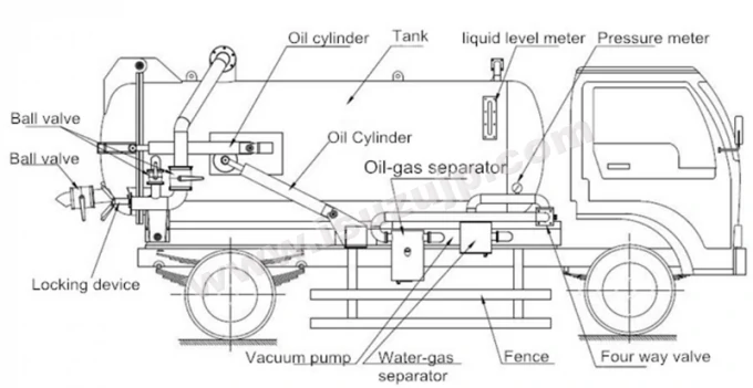
Design drawing of sewer vacuum suction truck:
Installation and precautions for a vacuum truck suction pump for sewage trucks
- 1. The vacuum pump’s bottom surface is located on the bottom of both the suction and discharge top. The axis of power take-off’s output shaft determines the height of the vacuum pump. The principle and the schematic diagram are used to guide their installation.
- 2. The vacuum pump’s power is generated by the power take off at the power window of the automobile gearbox. The driver controls the handle from the cab and uses the power take off gear to combine the gearbox gear and the shift fork to drive the vacuum pump.
- 3. The schematic diagram shows how to install the double pump. To avoid interference, the intermediate joint between the four-way valve and the two pumps suction pipe and two pump oil and gasoline separator outlet pipes should be in the middle.
- 4. Installation of the oil and gasoline separator should not be done at high or low pressure. The oil outlet of an oil separator should not be lower than the oil inlet at either end of the pump.
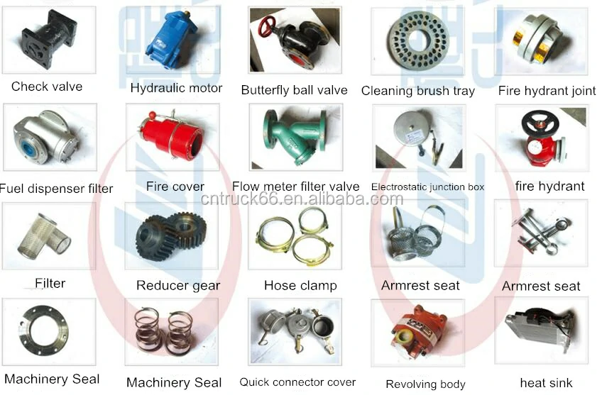
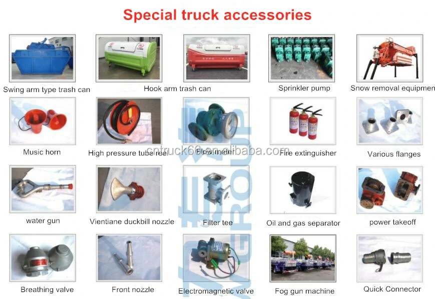
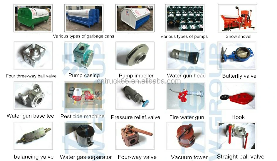
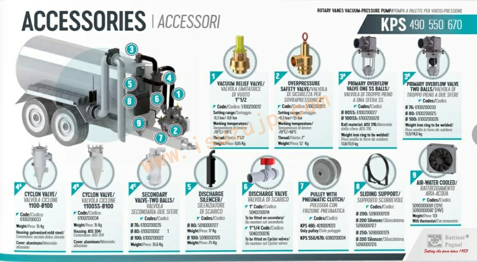
Other truck accessories catalog:
